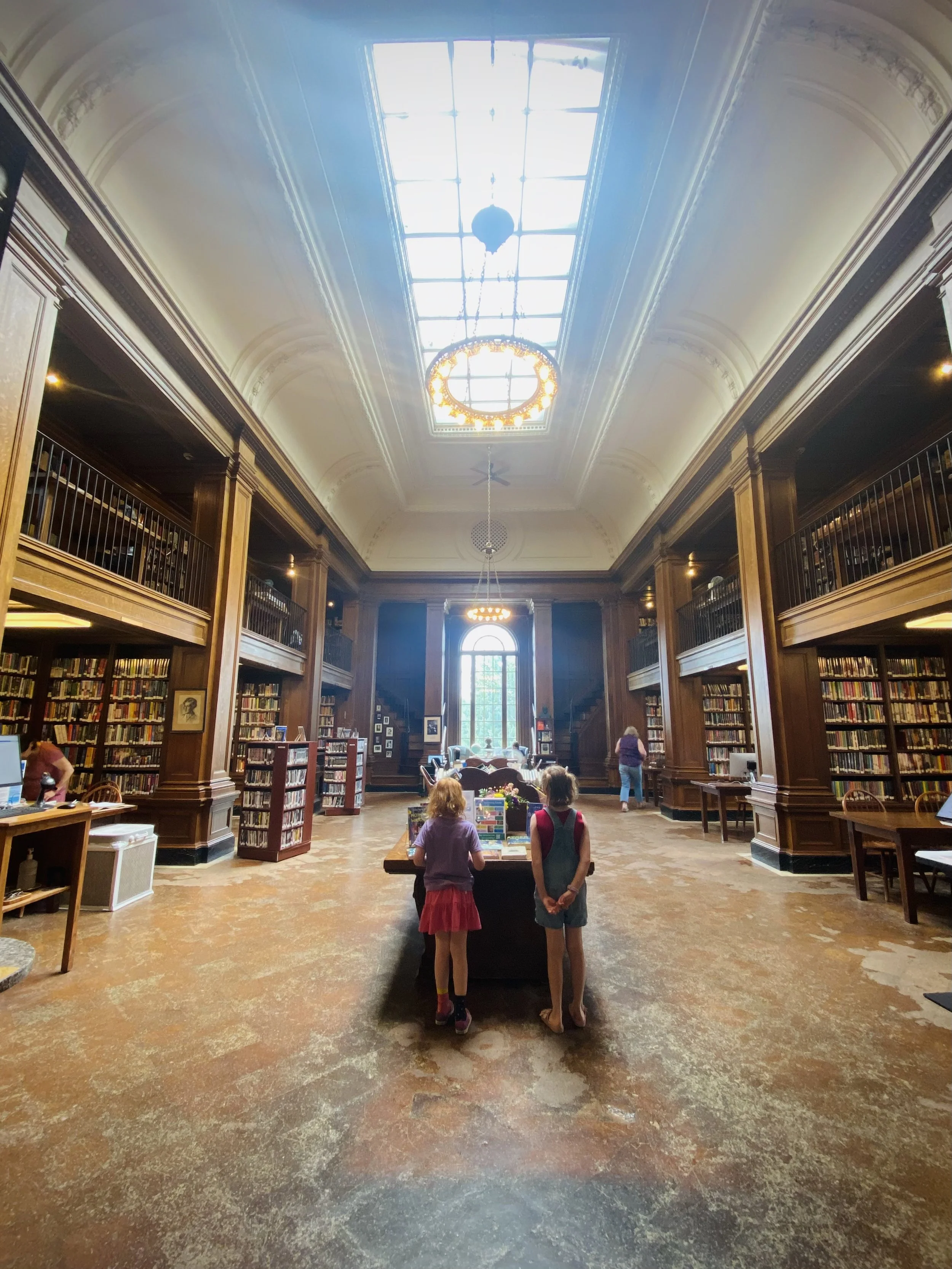
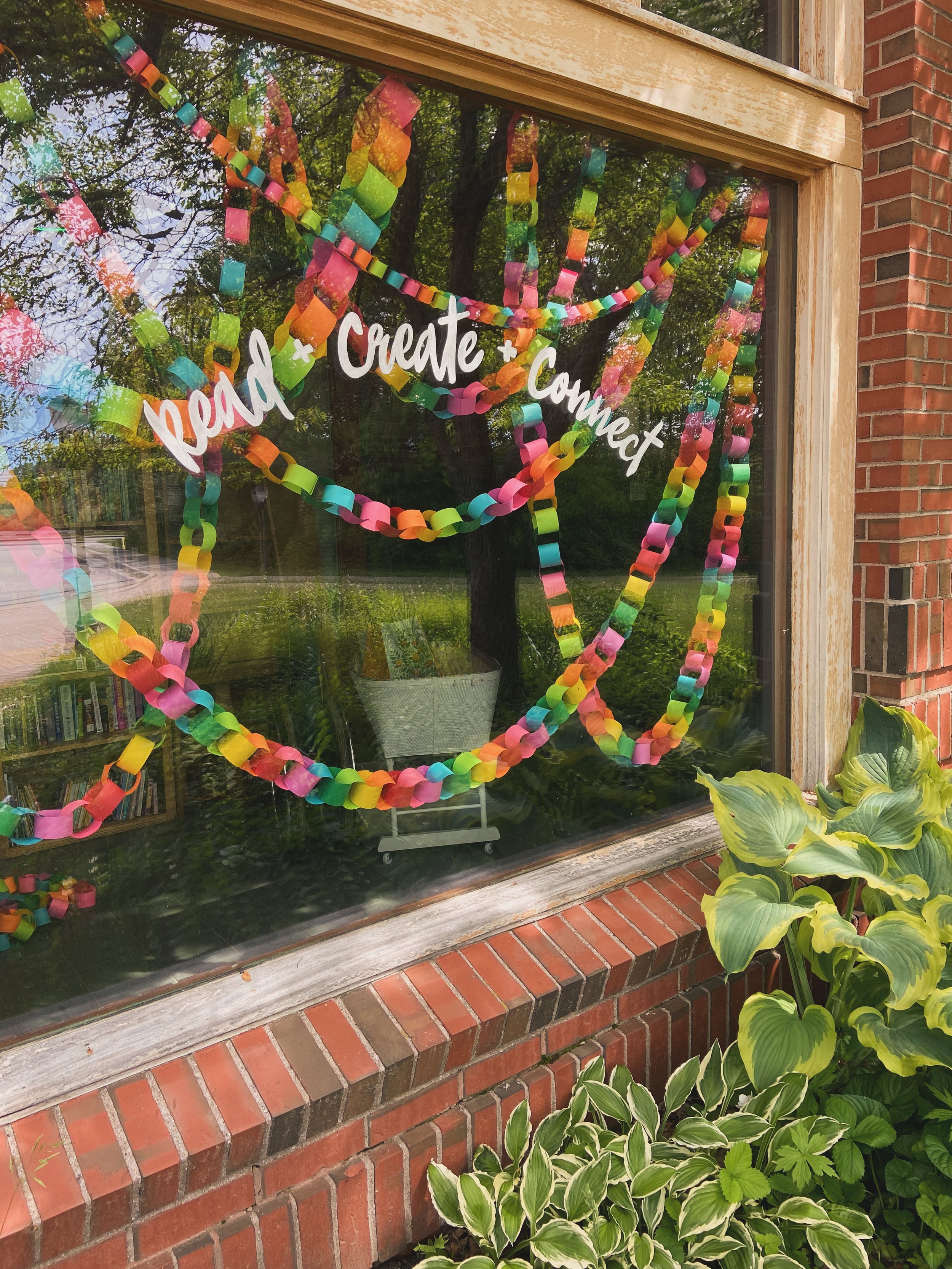
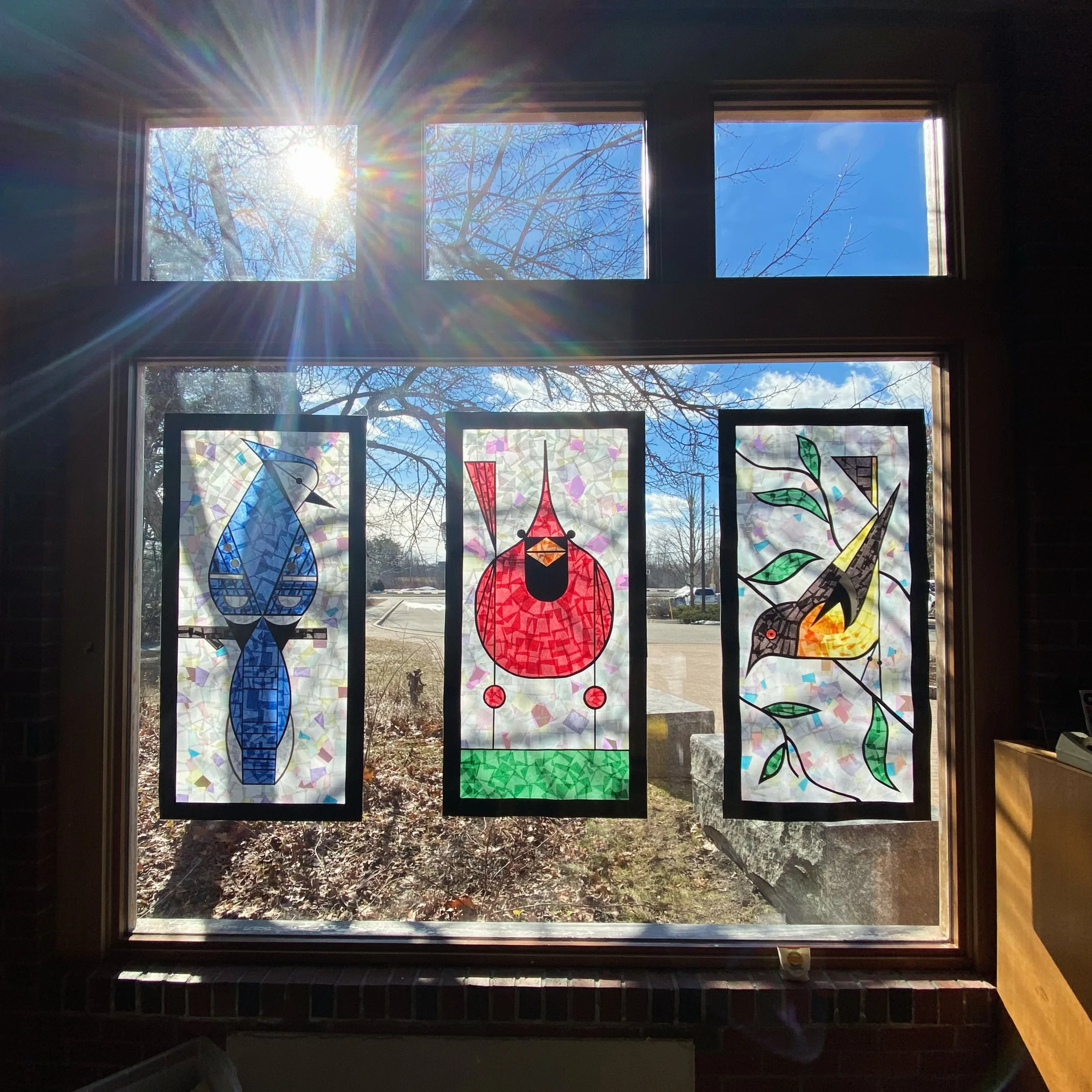
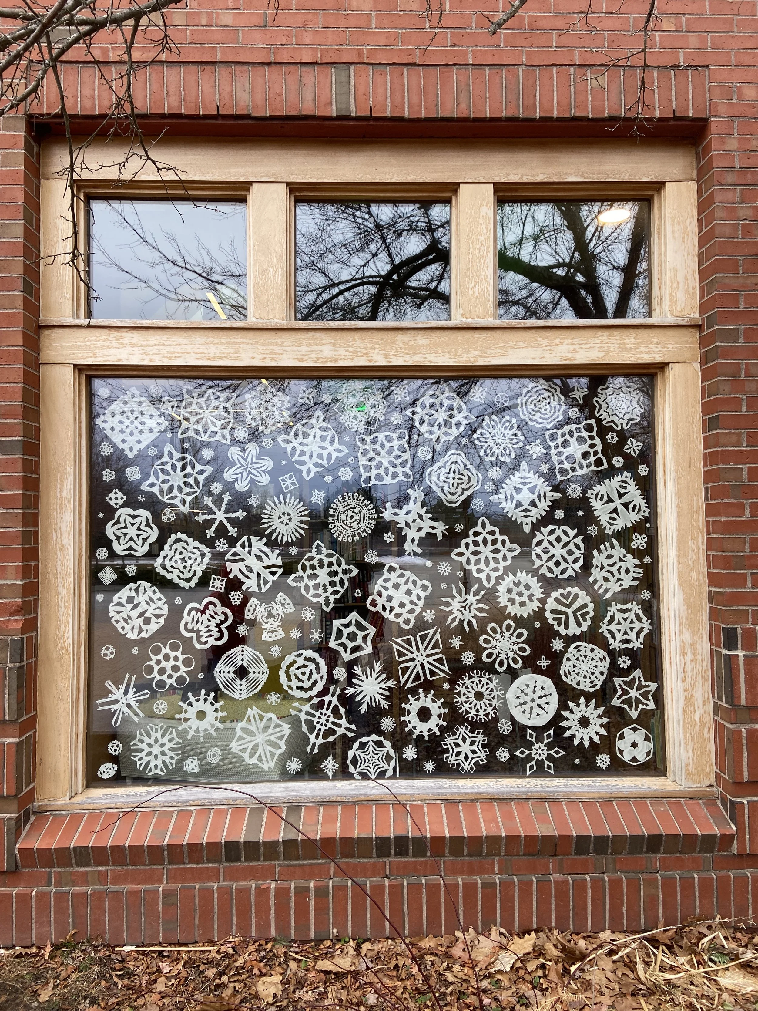
No results found library tourism Kathryn Swayze 7/17/26 library tourism Kathryn Swayze 7/17/26 Jesup Memorial Library Read More windows Kathryn Swayze 7/16/26 windows Kathryn Swayze 7/16/26 Summer ‘26 Window Read More windows Kathryn Swayze 7/15/26 windows Kathryn Swayze 7/15/26 Spring ‘26 Window Read More windows Kathryn Swayze 7/14/26 windows Kathryn Swayze 7/14/26 Winter ‘25 Window Read More windows Kathryn Swayze 7/13/26 windows Kathryn Swayze 7/13/26 Fall ‘25 Window Read More windows Kathryn Swayze 7/12/26 windows Kathryn Swayze 7/12/26 Summer ‘25 Window Read More
library tourism Kathryn Swayze 7/17/26 library tourism Kathryn Swayze 7/17/26 Jesup Memorial Library Read More